EMT16X 10 Million stitch maintenance (Monthly)
Video Demonstration:
Please follow all of the maintenance procedures carefully and apply the proper amounts of the specified lubrication during each step.
Melco cannot be held responsible for any machine damage due to lack of or wrong type of lubrication. Melco cannot be held responsible for any machine damage due to not following the listed maintenance steps.
You will now be guided through the 10,000,000 stitch maintenance procedure covering the following:
– X-Drive Rails
– Y-Bearing Blocks
– X-Cable Tension (Test)
– Grabber Eccentric

WARNING!
If you currently have a hoop or clamping system on the machine, please remove it.
Failure to fully remove a clamping system can result in damage to
the machine. When you press on the next button, the machine will move to the
appropriate position.

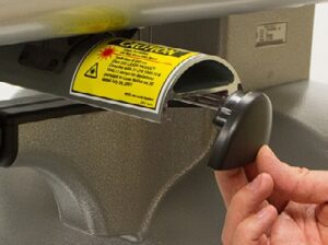
Remove End Cap Cover (Right)
Remove the end cap cover on the right side of the x-beam as
shown in the image.
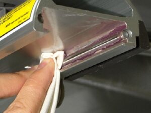
Clean Rails (Right)
Wipe any lint, dust, and old grease from the front and back steel
rails inside the x-beam as shown in the image.
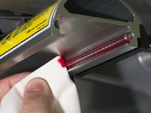
Grease Rails (Right)
Using a clean piece of cloth, apply a thin film of HP grease to the front and back steel rails inside the x-beam as shown in the image. Replace the end cap cover that was previously removed. When you press the next button, the machine will advance to the next maintenance position.
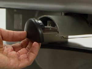
Remove End Cap Cover (Left)
Remove the end cap cover on the left side of the x-beam as shown
in the image.
Clean Rails (Left)
Wipe any lint, dust, and old grease from the front and back steel
rails inside the x-beam as shown in the image.
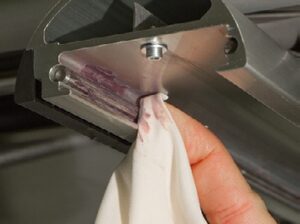
Grease Rails (Left)
Using a clean piece of cloth, apply a thin film of HP grease to the front and back steel rails inside the x-beam as shown in the image. Replace the end cap cover that was previously removed. When you press the next button, the machine will advance to the next maintenance position.
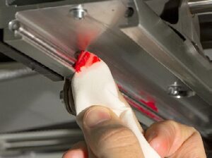
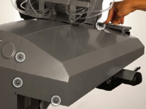
Remove Cover (Left)
Using a 3mm Allen wrench, loosen and remove the four (4) screws securing the left side cover as shown in the image.
Note: The screw in the lower outer rear corner of the cover is slightly longer than the other three (3) screws. Ensure that you use the same size screws for each hole later in this procedure. Remove the left side cover from the machine.
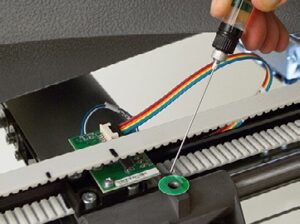
Oil the Bearing Block (Left)
Using a small oiler bottle, place twenty-five (25) drops of sewing machine oil into the oiling port as shown in the image.
Note: You may need to add a few drops and wait before adding more to prevent the oiling port from overflowing.
Replace Cover (Left)
Position the left side cover in its original location on the machine as shown in the image. Loosely install the front (shorter) mounting screw to hold the cover in place.
Install the other two (2) shorter mounting screws in the rear two holes near the center of the machine. The longer of the screw secures the lower outside rear corner of the cover. Carefully tighten all four (4) screws enough to secure the cover in place. When you press the next button, the machine will move to the
next maintenance position.
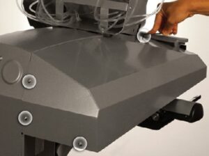
Remove Cover (Right)
Using a 3mm Allen wrench, loosen and remove the four (4) screws securing the left side cover as shown in the image.
Note: The screw in the lower outer rear corner of the cover is slightly longer than the other three (3) screws. Ensure that you use the same size screws for each hole later in this procedure. Remove the left side cover from the machine.
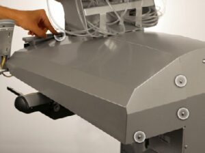
Oil the Bearing Block (Right)
Using a small oiler bottle, place twenty-five (25) drops of sewing machine oil into the oiling port as shown in the image.
Note: You may need to add a few drops and wait before adding more to prevent the oiling port from overflowing.
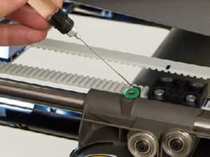
Position Gauge
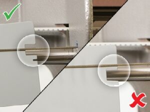
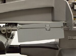
Position the x-cable tension gauge (P/N 33909) on the x-cable as shown in the image.
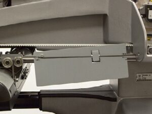
Test Tension
If the x-cable is positioned within the large cut-out on the right side of the x-cable tension gauge as shown in the image, the tension is within specification. If this is the case, press on the in specification button to continue.
If the x-cable is not positioned within the large cut-out on the right side of the x-cable tension gauge as shown in the image, the tension is out of specification and needs adjustment. If this is the case, press on the out of specification button to continue.
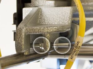
Locate Adjustment Nut
Locate the M4 nut and the x-cable tension stud and the end of the x-cable where it mounts to the front of the upper arm as shown in the image.
Press the next button to continue.
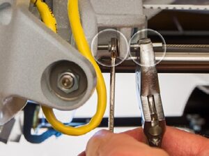
Adjust Tension
Using a 7mm wrench, grip the M4 nut and with a pair of pliers or adjustable wrench, grip the x-cable stud at the end of the x-cable as shown in the image.
To increase tension, rotate the M4 nut with the wrench counterclockwise while holding the x-cable stud with the pliers or adjustable wrench. When the x-cable is roughly at the lower edge of the cut-out on the right side of the tension gauge, remove the wrench, pliers and the tension gauge.
Press the next button to continue.
Remove Gauge
Remove the x-cable tension gauge before proceeding.
Press the next button to continue.
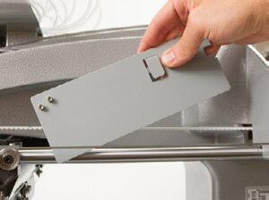
WARNING: If you proceed without removing the x-cable tension gauge, damage to your machine will occur and a service call will be necessary.
Note: Melco will not be responsible for any damage to the machine or related service costs caused by not removing the tension gauge.
When you press the next button, the machine will move to redistribute the tension along the x-cable. Press the next button to confirm that you have removed the gauge and continue.
Reposition Gauge
Reposition the x-cable tension gauge on the x-cable as shown in the image.
Press the next button to continue.
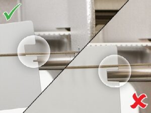
Test Tension
If the x-cable is positioned near the lower edge of the large cutout on the right side of the x-cable tension gauge as shown in the image, the tension is within specification. If this is the case, press on the in specification button to continue.
If the x-cable is not positioned near the lower edge of the cut-out on the right side of the x-cable tension gauge as shown in the image, the tension is out of specification and needs adjustment. If this is the case, press on the out of specification button to continue.
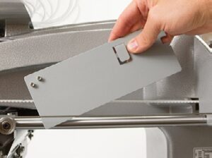
Remove Gauge
Remove the x-cable tension gauge before proceeding.
Press the next button to continue.
WARNING: If you proceed without removing the x-cable tension gauge, damage to your machine will occur and a service call will be necessary.
Note: Melco will not be responsible for any damage to the machine or related service costs caused by not removing the tension gauge.
When you press the next button, the machine will move to redistribute the tension along the x-cable. Press the next button to confirm that you have removed the gauge and continue.
Replace Cover (Right)
Position the left side cover in its original location on the machine as shown in the image. Loosely install the front (shorter) mounting screw to hold the cover in place.
Install the other two (2) shorter mounting screws in the rear two holes near the center of the machine. The longer of the screw secures the lower outside rear corner of the cover. Carefully tighten all four (4) screws enough to secure the cover in place.
When you press the next button, the machine will move to the next maintenance position.
Press the next button to continue.
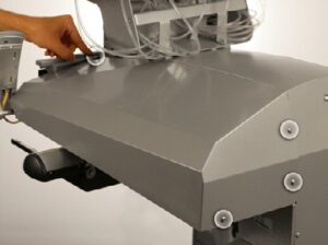
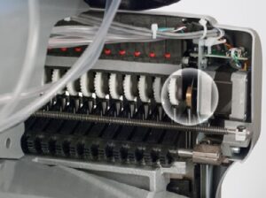
Locate Grabber Eccentric
Locate the grabber eccentric on the upper left back side of the needlecase as shown in the image.
Press the next button to continue.
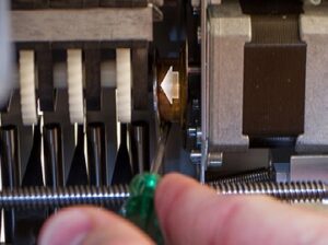
Move Lever
With a small flat blade screwdriver, carefully move and hold the grabber connecting lever over to the left as shown in the image.
Press the next button to continue.
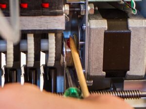
Grease Eccentric Surface
Using the grease applicator, apply a small amount of HP grease onto the grabber eccentric surface between the grabber connecting lever and the grabber home flag as shown in the image.
IMPORTANT: Ensure that no grease is applied to the black grabber flag on the right side. Once the grease has been applied, release the grabber connecting lever and remove the small screwdriver. When you press the next button, the machine will return to its original position.
Press the next button to continue.
Finished!
This completes the 10,000,000 maintenance procedure.
Press the finish button to exit the maintenance procedure.

